BEAGLEBONE BLACK BARE METAL DEVELOPEMENT
2014-12-08

Not so long ago, I wrote a small OS prototype for the Cortex-A8 CPU. I was using qemu but now I wanted to play with a real device.
So I decided to give it a shot with my BeagleBone Black.
Booting
The beaglebone black's AM3359 chip has an internal ROM (located at 0x40000000) that contains boot code.
That boot code will attempt to boot from many sources but I am only interested in the eMMC booting.
The boot code will expect the eMMC to be partitioned and that the first partition is FAT32. I don't
know if there is anyway to just use the eMMC as raw memory and have the AM3359 boot code to just load
whatever is at the bottom of the flash without any partitions, so I will live with the FAT32 concept.
I want to use u-boot because I want to be able to update my kernel with tftp. The stock BBB will have
the eMMC formatted with a FAT32 partition with uboot on it. I will make a u-boot script that
downloads my kernel from the tftp server, copy it in flash memory and then have u-boot load that
kernel from flash memory into RAM. That last step is not necessary but I want to do it because at a later
point in time, I will remove the tftp part from the u-boot script and only have the kernel in flash be loaded
in RAM.
The proper way to do this, would be to store the kernel file and all of my application files in the ext2 partition
that is already present in the eMMC. But then, I would need a EXT2 driver in my kernel so that it could
load the application files from the flash. I don't wanna bother writing a ext2 driver for now so I will hack my way
though this instead. So instead of getting uboot to download the kernel and applications in a eMMC partition,
I will get it to write the kernel at a fixed location (0x04000000) in the eMMC. This will most probably overwrite
a part of the 1st or second partition but I really don't care at that point. As long as I don't overwrite
the partition table and the begining of the FAT32 partition where u-boot sits. Then all applications
will be written one after the other just after the kernel in a linked-list style.
According to section 2.1 of the TI reference manual for the AM335x, the ROM starts at 0x40000000. But then, in section
26.1.3.1, they say that the ROM starts at 0x20000. This is very confusing. It turns out that when booting, memory location
0x40000000 is aliased to 0x00000000. The CPU starts executing there, and some ROM code jumps to the "public ROM code". The public ROM code starts at ROM_BASE+0x20000. Since memory is aliased, 0x200000 is the
same as 0x40020000. Section 26.1.4.2 says that the ROM code relocates the interrupt vector to 0x200000, probably using
CP15 register c12. When the ROM code finds the x-loader (MLO) in flash memory, it loads it in SRAM at 0x402F0400. At this point, system behavior is defined by u-boot (MLO was built with u-boot).
What was confusing me at first was that I thought that the eMMC mapped to 0x00000000. Turns out that this memory
is not directly addressable. So if I need to retrieve my applications from eMMC, I will need to write a eMMC driver
because the eMMC is only accessible through EMMC1. Now that I understand how eMMC works, I realize that it was foolish
of me to think that it could be directly addressable. The MMC1 peripheral will allow you to communicate with the on-board
eMMC but you still need to write your own code to interface it using the SD/MMC protocol.
I had a really hard time finding information on how to read the eMMC. The TI documentation is good at explaining how to use the
MMC controller but they don't explain how to actually communicate with the eMMC. And that's normal since the eMMC is board dependant.
The eMMC is accessible through MMC1. The TI documentation explains how to initialize the device but since we know that the
board contains eMMC, we don't have to go through all the trouble of detecting card types etc. I was really surprised of
how it was hard to find good documentation on how to use the MMC/SD protocol. I can't really explain what I did, all I know
is that it works, and the code will definitely not be portable to another board. I read the TRM and also looked at another source code
and trought trial and error, I was able to read the eMMC. The file emmc.S in my source code is pretty easy to understand. I was not able to send the proper command to set the device in "block addressing mode" and to change the bus
width. Like I said, this information is kinda hard to find. I'll have to do a lot more researching to make this work.
I want uboot to download my kernel from tftp and load it in memory. There doesn't seem to be
any easy way to do this. I couldn't find a way to install uboot on my BBB without installing
a full eMMC image containing linux. So I decided to just use the stock eMMC image but modify uboot
to boot my kernel instead of the installed linux. But it seems that changing the environment
variable "bootcmd" is impossible from uboot on the BBB. But there is the uenv.txt file
residing on the FAT partition that I can change to contain my own script to download my kernel.
Well, that to is impossible to modify directly from uboot.
So I ended creating an SD card with an angstrom image, boot from the SD card, mount the eMMC FAT32 partition
and edit the uenv.txt file. I modifed it to look like this:
uenvcmd=set ipaddr 192.168.1.37;set serverip 192.168.1.3;tftp 0x80000000 os.bin;tftp 0x90000000 apps.bin;mmc dev 1;mmc write 0x90000000 0x28000 0x100;go 0x80000000
Now everytime I want to update the uenv.txt file, I need to boot from the SD card because I am destroying the 2nd partition
on the eMMC with my kernel since I use raw writing on the eMMC. This is not a nice solution but it works for now
Software IRQ
The software IRQs on the BBB work in a completely different way than the realview-pb-8 board.
On the BBB, software IRQs are not dedicated IRQs. You get a register that allows you to trigger an IRQ
that is tied to a hardware IRQ already. So You can only use software IRQ to fake a hardware IRQ. This means
that you could send a software IRQ 95 but that would be the same as if you would get a timer7 IRQ. You
actually need to unmask IRQ 95 for this to work, but unmasking IRQ 95 will also allow you to get TIMER7 IRQs.
In my case, this is excellent. Because my timer7 IRQ calls my scheduler code. So a Yield() function would just
trigger that IRQ artificially using the software IRQ register.
User-mode handling of IRQs
User-mode threads can register interrupt handlers in order to be notified when GPIO is triggered.
The way this works is that whenever an interrupt is received, if a user-handler is defined, then
the page table is changed to the page table base address of the thread that is interested in receiving
the event. Then, a jump to the handler is done. So the CPU stays in IRQ mode, but the page table is changed
and the user-mode handler is executed in IRQ mode.
The code
There is a lot more I could describe in here but the source code might a better source of documentation. Basically, other things I have
accomplished is:
- AM3358 interrupt controller
- AM3358 timer
- SPI driver for a port expander (MCP23S18) and for an EEPROM chip (25aa256)
- Pin muxing
- GPIO (output and input with interrupts)
- sending data on more than one UART.
https://github.com/pdumais/bbbos
ARM BARE METAL DEVELOPMENT
2014-11-01
The project
I've always wondered how programming for an ARM cpu is. So I decided to try to make an OS, written
100% in assembly for an ARM development board. I shouldn't say OS though, every time I write
an OS, I really only make: memory management, scheduler, mutex, netcard driver, serial port driver and
some small application to run on the "os". It's basically just to learn about the architecture
of the device.
The ARMv7 architecture offers a lot of cool features that I am not using. I just want to keep things simple for now.
Once I get something working good, I will go deeper in the documentation and try some more advanced stuff.
At first, I wanted to use my beaglebone black to run my OS. But then, I found out that
qemu can emulate quite a few boards and it would be easier to do. By using qemu, I get the following
advantages over using a real board:
- no need to upload code to the board, I use the image directly
- can reboot the machine easily while working remotely (no need to physically access the board)
- very easy to peek in memory with qemu's monitor command "pmsave"
- can use gdb to debug with qemu
- no need for a separate bootloader. Can boot kernel directly.
I chose to use the "realview-pb-a8" emulated board in qemu. I have never seen
that board, I have no idea what it is. It uses a Cortex-A8. So I was able to get a programing
guide for that SoC. I started from there.
The fact that I am using qemu makes things easier but removes a lot of fun. For example, qemu boots my kernel
directly. On a real board, I would need to write a bootloader (or use u-boot). I would need to initialized
SDRAM, initialize clocks and "power domains" and other board initialization. QEMU boots your kernel directly
into RAM and you can run from there. So I wouldn't quite call this "bare-metal" programming. I guess
I could only call this project "kernel programming for a Cortex-A8".
Getting started
The first step is to create a small test and actually run it. So I created the following program:
Note the qemu command in the Makefile. This allows me to run the test using "make run". It will emulate the ARM board which is the realview-pb-a8
Board specifications
When starting development on a new board, the first thing you need to do is to get a memory map of the device.
Because the board will contain sdram, sram, memory mapped peripheral IO etc... From board to board, the
physical location of those elements will change. Here is the memory map for the realview-pb-a8
Physical Memory Layout
| Physical address | Description |
|---|
| 0x00000000-0x0FFFFFFF | SDRAM mirror |
| 0x10000000-0x1001FFFF | Peripherals |
| 0x10020000-0x1005FFFF | Board specific stuff that I don't need just yet |
| 0x10060000-0x1007FFFF | On board SRAM |
| 0x10080000-0x6FFFFFFF | Board specific stuff that I don't need just yet |
| 0x70000000-0x8FFFFFFF | SDRAM |
| 0x90000000-0xFFFFFFFF | Board specific stuff that I don't need just yet |
A more detailed memory map can be found in the RealView Platform Baseboard for Cortex A8 User Guide.
Booting
Interrupt vector table
This architecture only uses 7 interrupt vectors
| 0x00 | Reset |
| 0x04 | Undefined Instruction |
| 0x08 | Software Interrupt |
| 0x0C | Prefetch Abort |
| 0x10 | Data Abort |
| 0x14 | reserved |
| 0x18 | IRQ |
| 0x1C | FIQ |
The interrupt vector table must be placed at the begining of the memory. Each entry is 32bits wide.
It must be an instruction not an address. So you would typically put a branch instruction to jump
to the proper handler. Using qemu, my kernel gets loaded at 0x70010000, so putting the IVT at the begining
of my kernel would not work. I had to rellocate the IVT to 0x70000000 once the kernel was running. By the way,
on that board the SDRAM starts at 0x70000000 but is mirrored to 0x00000000. Still, qemu starts execution at 0x70010000.
but if the IVT is at 0x70000000, the CPU will still see it at 0x00000000 because of the mirror.
Setting up the stack
There are 6 CPU modes in this architecture. Each mode will shadow the register r13 (stack pointer). So
they each need their own stack. To set those stacks, you must switch mode and set r13 appropriately. I don't
set the User mode stack because this will be done on a per-process basis and System mode uses the same registers
as user mode.
    msr     CPSR_c,#0b11010001           // stack for FIQ mode
    ldr     r13,=STACK_BASE_FIQ
    msr     CPSR_c,#0b11010010           // stack for IRQ mode
    ldr     r13,=STACK_BASE_IRQ
    msr     CPSR_c,#0b11010111           // stack for Abort mode
    ldr     r13,=STACK_BASE_ABORT
    msr     CPSR_c,#0b11011011           // stack for Undefined mode
    ldr     r13,=STACK_BASE_UNDEFINED
    msr     CPSR_c,#0b11010011           // stack for Supervisor mode. And we will stay in that mode
    ldr     r13,=STACK_BASE_SUPERVISOR
Memory Management Unit
Creating a paged memory system is not difficult. The MMU offers a 2 level page table system
The level1 table has 4096 entries, each mapping 1Mb of virtual addresses.
You could create "section" entries to map those 1Mb to physical memory directly. You would
then get pages of 1Mb and only 1 table that takes 16k in memory. But if you want 4k pages, then
those entries need to be "Coarse table" entries, meaning that each entry will reference
a subtable (a level2 table). Each level 2 table contain 256 entries, mapping 4k of memory.
So for a 4k paging system you would have 1 Level1 table with 4096 entries (a total of 16k in size)
and 4096 level2 tables containing 256 entries each for a total of 4Mb in size.
| Level1, Section |
|---|
| 31 | 30 | 29 | 28 | 27 | 26 | 25 | 24 | 23 | 22 | 21 | 20 | 19 | 18 | 17 | 16 | 15 | 14 | 13 | 12 | 11 | 10 | 9 | 8 | 7 | 6 | 5 | 4 | 3 | 2 | 1 | 0 |
|---|
| base addr | NS | 0 | nG | S | AP2 | TEX | AP | 0 | domain | XN | C | B | 1 | PXN |
| Level1, Page Table (TODO) |
|---|
| 31 | 30 | 29 | 28 | 27 | 26 | 25 | 24 | 23 | 22 | 21 | 20 | 19 | 18 | 17 | 16 | 15 | 14 | 13 | 12 | 11 | 10 | 9 | 8 | 7 | 6 | 5 | 4 | 3 | 2 | 1 | 0 |
|---|
| page table addr | 0 | domain | 0 | NS | PXN | 0 | 1 |
| Level2, Small Page (TODO) |
|---|
| 31 | 30 | 29 | 28 | 27 | 26 | 25 | 24 | 23 | 22 | 21 | 20 | 19 | 18 | 17 | 16 | 15 | 14 | 13 | 12 | 11 | 10 | 9 | 8 | 7 | 6 | 5 | 4 | 3 | 2 | 1 | 0 |
|---|
| base addr | nG | S | AP[2] | TEX | AP[1:0] | C | B | 1 | XN |
Domains and permissions
The mmu has a concept of domains and access permissions.
16 access domains exist. In a page descriptor, we set the access bits and the domain associated
with that page. CP15.register3 contains 2 bits for each domains 0 to 15. These bits
determine how page access should be checked. Example: a page is associated to domain 12.
CP15.register3 indicates that domain12 is Client. Therefore access permissions in the page
will be checked. If domain12 was set to Manager, permissions would have been ignored.
Initializing the MMU
The first thing you need to do is setup the page tables like mentionned above.
Obviously, you might want to do an identity mapping for the region of code that
is currently running the MMU initialization code so that the mapping does not change
after having initialized the MMU.
Level 1 Page Table
70100000  01 40 10 00 01 44 10 00  01 48 10 00 01 4c 10 00
70100010  01 50 10 00 01 54 10 00  01 58 10 00 01 5c 10 00
...
70103fe0  01 20 50 00 01 24 50 00  01 28 50 00 01 2c 50 00
70103ff0  01 30 50 00 01 34 50 00  01 38 50 00 01 3c 50 00
Level 2 Page Tables (all contiguous)
70104000  fe 0f 00 00 fe 1f 00 00  fe 2f 00 00 fe 3f 00 00
70104010  fe 4f 00 00 fe 5f 00 00  fe 6f 00 00 fe 7f 00 00
...
70503fd0  f2 4f ff ff f2 5f ff ff  f2 6f ff ff f2 7f ff ff
70503fe0  f2 8f ff ff f2 9f ff ff  f2 af ff ff f2 bf ff ff
70503ff0  f2 cf ff ff f2 df ff ff  f2 ef ff ff f2 ff ff ff
Then you need to configure the CP15 register.
| Register | Description | Value |
|---|
| CP15.reg2 | Translation Table Base Register | Load the base address of the Level1 table |
| CP15.reg3 | Domain Access control register | MCR p15, 0, , c3, c0, 0 where Rd contains the 32bits we want to write.
We will use domain 0 for the kernel for now. So bit 1:0 will be set to 0b11 to allow access without checking permissions.
all other domains will be set to 0b00 to unconditionally deny access. |
| CP15.reg1 | Control | Set bit0 high to enable the MMU. Do this as the last step |
The following registers are also useful but not needed during initialization
| CP15.reg5 | FSR | Read this in you fault hander. It is the fault code |
| CP15.reg6 | FAR | Read this in you fault hander. It is the faulty virtual address |
| CP15.reg8 | Invalidate TLB | Used to invalidate the TLB. invalidate entire TLB: mcr p15, 0, Rd, c8, c7,0 |
| CP15.reg10 | TLB Lockdown | Used mark a TLB entry as persistent so it does not get overwritten by other entries.
can increase performance for pages such as those containing interrupt handling code so that
the translation is always cached.
We could probably use a level1 table entry as a Section of 1Mb for the kernel
and lock it down in the TLB. |
Faults
I will not list the different reasons for getting a fault since this is all covered
in the reference manual. Basically, if a fault occurs while prefetching an instruction
then the Instruction Fetch fault will occur. If the fault occurs while accessing data, a
Data fault will occur. The virtual address that caused the fault will be stored in FAR.
A more detailed error code will be found in FSR
Processes
To test the multitasking system, I have created some small programs that I build separately
and package in the image. The kernel loads the programs in their own process. Ideally, I would
have like to create a flash image that contains the kernel at the very begining and then
the programs would be appended at the end, kind of like a real hard disk with a bootloader
and programs. But I could never get qemu to eumlate a flash file. Even with the "-pflash".
The documentation for the board says that when the board is powered on,
the flash is mapped at 0x00000000. This will shadow the sdram. To use the sdram,you must remap
the flash to some other place.
But I could never make that work. I tried creating a flash image and provide it
to qemu with the "-pflash" option but that doesn't seem to work. Qemu always wants a kernel file to be
provided. I don't know why I can just put my code in a flat binary that would act as flash and get
the code running from 0x00000000. The kernel file gets loaded at 0x70010000 which is the sdram.
So I am creating a image file containing the kernel and the programs that get loaded in sdram
by qemu.
Programs run as domain 1, and in user mode. Their virtual mapping is:
| Level1 table entries (1mb mapping) | Type | Permissions | Description |
|---|
| 0 | Section | PL1 RWX, PL0 - | Kernel code. Identity mapping |
| 1-FF | Section | PL1 -, PL0 - | Unmapped |
| 100 | Page table | PL1 RW, PL0 - | peripherals, and SRAM. Identity mapping |
| 101-1DF | Section | PL1 -, PL0 - | Unmapped |
| 1E0 | Page Table | PL1 RW, PL0 - | Peripherals. Identity mapping |
| 1E1-1FF | Section | PL1 -, PL0 - | Unmapped |
| 200-2FF | Page Table | PL1 RWX, PL0 RWX | Process code |
| 300-6FF | Section | PL1 -, PL0 - | Unmapped |
| 700-8FF | Section | PL1 RWX, PL0 - | Kernel code. Identity mapping |
| 900-EFF | Section | PL1 -, PL0 - | Unmapped |
| F00-FFF | Page tables | PL1 RW, PL0 RW | Process Stack |
The task information page
When creating a process, I add it in a list of process. The list of process is a fixed-size list in kernel
memory (accessible by any process in privileged mode) that contains a pointer to the L1 table of the process
and several other usefull information for the process.
This information is used by the scheduler and is formatted like this:
| Offset | Description |
|---|
| 0x0000 | Physical address of the process's L1 page table |
| 0x0004 | saved r13_irq registers |
| 0x0040 | Quantum count |
Using Software Interrupts
When using the SWI instruction, you need to pass it a parameter that would normally be the function number
you would want to call. For example: SWI 0x02. Once you are in the SWI handler, you want to get that parameter
to know where to dispatch the handler. but the SWI instruction completely ignores the parameter. It is not
given to you in any way when you get in your handler. In order to get this, you need to take r14, which
contains the return address and substract 4. That would give you the address of the SWI instruction
itself. So you can read at that memory area and see what parameter was provided. That is pretty weird in
my opinion. I would rather just put the function number in r0 before calling SWI and read r0 once in the
handler. That would illimnate an unncessary memory access. Plus, the page at that location
will obviously be in the instruction prefetch cache but since we are using "LDM" to load the instruction
in a register to read it, it means we will be looking in the data cache. And the page will most probably
not be in that cache. So in my project, I will only pass function parameters in a register and ignore
the one provided to SWI.
Something that confuses me is that when calling SWI, you enter Supervisor mode. Then you are in privileged mode.
That makes sense, But then r13 and r14 gets shadowed. I'm not entirely sure why I would want that. It actually
complicates things when multi-tasking. I guess that in some more complex OS design, this is very usefull.
Multi-Tasking
Saving registers of mode X from mode Y
Assume we have a function called schedule(). This function saves the current context, and reloads
the context of the next task to run. In my implementation, this function willa lways be called
from the IRQ mode. So the schedule function will be called from a non-user mode.
The schedule function will need to store the user-mode context (registers r0 to r14).
But from the non-user mode of IRQ, registers r13 and r14 are shadowed. r0-r12 will
be the same as the user-mode so we need to find a way to save the r13 and r14 of the user mode.
For this, the instruction stm/ldm with "^" can be used to store/load the user-mode registers.
this will save/load r0-r12 as usual but the r13 and r14 will be the ones of the user mode.
CPSR and SPSR:
While in an exception (therefore in a mode different than user or system) the previous
cpsr is saved in spsr. Before returning back from the exception, you must reload spsr back
into cpsr. This will change the mode automatically, re-enable interrupts etc. To load this
and to load r14 in r15 at the same time, look at the notes below about the LDM instruction.
LDM instruction format:
Compared to AVR32 and x86, this is pretty complicated in my opinion. The "ldm" instruction has 3 forms.
The first form does what it says it does. But the second form which is: ldm Rn,registers_without_r15^
(yes, there is a "^" at the end) loads all user mode registers while you are in a non-user mode.
so it is a way to load user registers while they are shadowed.
The third form, ldm Rn,registers_with_r15^, will automatically load spsr back into cpsr.
You could also use a data instruction with the "S" flag and R15 as a destination. For some
reason, it will conveniently reload spsr back into cpsr at the same time... Go figure.
For example: movs r15,14; will reload r15 and also reload spsr back into cpsr.
I am wondering why they re-purposed a flag like this. That is one small thing that makes me like x86 more than ARM.
Since I re-enable interrupts after entering SWI, the SVC context must be saved also since a context switch could
occur while in a service call (that is actually the whole point of re-enabling interrupts in SWI). So
my context-switching code also pushes the r13_svc and r14_svc on the the task's IRQ stack.
Context switching
The schedule function needs to do the following:
- save registers r0-r14 user-mode
- save register r14_irq (since this will be done from the IRQ handler)
- save register spsr (which is the usermode cpsr)
- change level1 page table for new process
- flush tlb (unless using ASID)
- restore r0-r14 (for user-mode)
- restore the return address in r14_irq
- restore spsr
- to return, load r14_irq in r15 and spsr into cpsr
Each task have their own stack and they have their own IRQ mode stack. When entering
the schedule() function in IRQ mode, the use-mode registers are pushed onto the IRQ stack.
The current spsr and r14_irq is also pushed on the IRQ stack. The r13_irq is then saved
in a list somewhere. When time comes to restore the task, the page tables are switched back
to that task's page tables, and r13_irq is restored from the list. At this
point, the task's IRQ stack has been restored. We can then pop everything from it
and the context switch is done. Here is a sample of my schedule function
    push(r0-r14)^
    mrs     r0,SPSR
    push(r0)
    // At this point, whole context is saved on stack


    // Determine what is the next task to run
    ...

    // store context: save r13_irq
    // r0 points to the entry in the process list (as decribed earlier)
    str     r13,[r0,#4]     // offset 0x04 is r13

    // load new page table
    ldr     r1,[r5]             //r5 points to the entry of the next task to run
    mcr     p15,0,r1,c2,c0,0
    // flush TLB (note that there are ways to avoid this
    mov     r1,#0
    mcr     p15,0,r1,c8,c7,0

    //load r13_irq
    ldr     r13,[r5,#4]

    // now restore context on stack
    pop(r0)            // this is just SPSR, only reg available to touch is r14
    msr     SPSR,r0
    pop(r0-r14)^
    b       returnFromInterrupt
This is a sample only. My schedule() function does a bit more than that. But it gives
you the general idea.
When r0-r14 will be restored for the user mode, it would restore the task's context as it
was before entering the IRQ to schedule(). r13 and r14 of the user mode will be restored
and not the banked ones of the currently executing mode.
Note that the TLB must be flushed when reloading the "translation table base register" in CP15
because the cached TLB entries will continue to correspong to the previous mapping. This is a very expensive operation but we can use the concept of ASID by using the CONTEXTIDR register. By setting
a unique task ID in CONTEXTIDR, all page translations that gets loaded in the TLB will be tagged with that ID. When doing a lookup, the MMU will ignore entries that do not match the current CONTEXTIDR. So on a context switch, you would change the ID in CONTEXTIDR. This would create duplicate entries in the TLB but with different IDs. So instead of flushing the TLB, entries will be removed only when the TLB is full. See this article for more information about the TLB and ASID.
The schedule() function is called by the timer IRQ handler. But you might want to call it from other places.
For example, if a task wants to yield, it should be scheduled out immediately. I could do this in a SWI handler
but trying to change context from the SVC mode brings up other challenges. So to keep things simple, I want
to do context switches only from the IRQ mode. For this, it is possible to use a "software IRQ". This is well
documented in the GIC documentation.
Download
Here is my source code
USING EPOLL
2014-10-10
Introduction
I heard about epoll not so long ago and wanted to give it a try. Epoll is the new
way to use non-blocking sockets (or any file descriptors). It replaces poll() and select().
epoll is easy enough to use. The good thing about it is that, unline select(), you don't need
to rebuild the FDSET each time you call epoll_wait. Here is a typical usage:
- efd = epoll_create1()
- epoll_ctl(efd, EPOLL_CTL_ADD, listeningSocket)
- loop:
- n = epoll_wait()
- for i=0 to n:
- if (events[i].data.fd == listeningSocket)
- newsock = accept()
- epoll_ctl(efd, EPOLL_CTL_ADD, newsock)
- close(efd)
Another nice thing about epoll is that you don't need to worry about removing a socket from the list.
You can call epoll_ctl(efd, EPOLL_CTL_DEL, sock) if you want but when the socket closes, it will
be removed automatically.
One thread
Using epoll, I can do all my sending and receiving in one thread. So people may suggest to
send data from other thread but what if you get EAGAIN? Assume that thread A is the epoll thread.
Thread B attempts to send 100 bytes but could only send 50. Then Thread C attempts to write 100 bytes
on the same socket. By the time that Thread C was called, the socket was ready. The remote socket
will have received corrupted data. For that reason, Thread B and C, will add data in a queue so that
each messages are guaranteed to be sent completely. The queue will be emptied in Thread A.
Since epoll might potentially handle thousands of connections, Thread A must do minimal work.
It must only do this:
- epoll_wait
- if a socket is ready-ready, read all from that socket and dispatch to consumers.
consumers should work fast, otherwise we should "post" the data to the consumer in another thread.
- send all from the sendqueue
Edge-triggered VS Level-Triggered
epoll offers two ways of working: Edged-triggered and Level-triggered. The default way is Level-triggered.
so you might want to change this to level-triggered in your application.
In Level-triggered mode, epoll will return as long a socket is read or write ready.
So if data is ready to be received on the socket and you only read part of it, the next epoll call
will return because there is still data available. As soon as the internal receive buffer is empty,
then epoll won't return. But since the socket will be write-ready almost all of the time, it will return.
This is not something you would typically want. My guess is that if you want to use level-triggered mode,
you should not register to get EPOLLOUT events unless you have something to send. So while your application's
TX buffer is empty, you don't register for EPOLLOUT. As soon as data is added to the TX buffer, you register
for EPOLLOUT, epoll will return and you write data out on the socket. If EAGAIN was returned then you will block
on the next epoll_wait() and can send the rest of the buffer when it unblocks. Once the application's TX buffer
is empty, you could unregister for EPOLLOUT.
With Edge-triggered mode, things are different. You will only receive an event if the status has changed from not-ready to ready.
So if you have incomming data and you only read part of it, when you will call epoll_wait, the socket will still be ready.
So epoll_wait will block because the state will not change from not-ready to ready. So if you are using that mode, you must
make sure to read ALL the data on the socket until you get EAGAIN. If you want to send something, epoll_wait will only give you
a write-ready event if you previously got EAGAIN while attempting to write out.
Let's say you have an internal transmit queue in which you add data when you want to send it out. The epoll thread would need
to ready from that queue, write the data on the socket and handle EAGAIN appropriately.
- epoll_wait()
- if a socket is ready-ready, readAllFromThatSocket(socket);
- sendAllData() // sends all that is contained in the internal queue.
- goto step 1
But if epoll_wait() is blocked in triggered mode, and you add data in the queue (from another thread), sendAllData() will not be called until
epoll_wait returns because data is ready to be received (it won't return because data is ready to write, because you need to write first and get EAGAIN for that.). To solve this problem, I created an eventfd (see sys/eventfd.h). I add the eventfd in the epoll_wait list and whenever I add
data in the application's TX queue, I write 1 on the eventfd so that epoll_wait will break out. I could have used a timout
in epoll_wait, but that would add unnecessary latency to amy reactor. That way of doing things is similar to what is called the "pipe to self trick".
My framework
To play with epoll, I wrote a small reactor framework that exposes an interface that's easy to use.
all the gory details are hidden inside the framework. To use it you would need to define two classes:
class OwnProtocolFramingStrategy: public IFramingStrategy
{
protected:
    virtual int processData(char* buffer, size_t size, FullMessageInfo& info)
    {
        info.buffer will first be zero. You need to allocate memory for that buffer
        and copy the data from "buffer" to "info.buffer". If you determine that the buffer
        does not contain a full message, return the quantity of bytes you read from the buffer.
        In this case, it should be "return size;" And the next time that some data is received,
        this function will be called with you buffer. You can update other fields in "info"
        to help you resume next time.

        If you determine that a full message was received, set "info.complete = true" and return
        the number of bytes that you read from the buffer. After returning from this function, your
        buffer created in "info.buffer" will be considered as containing a full message and will be
        passed to the TcpEngine. Next time this function will be called, info.buffer will be back to
        zero.

        If you determine that a full message was received but there are still data left in the buffer,
        it means that you probably have 2 messages in the buffer. As mentioned above, you will
        return the number of bytes that you read from the buffer. This function will be called
        again with "buffer" pointing to the index after the last byte you have read. So you
        only need to try to parse one message only when this function is called.

        If you find that data is not well-formed, does not respect you protocol or has any other errors
        that prevents you from reliably build a full message, then return -1 and the client's connection
        will be aborted.
    }
};
A IFramingStrategy is a class that will process the tcp stream into full messages. As you know, when
reading data from a socket, you may receive more than one message in a single read and you could also
only receive half of a message. So the IFramingStrategy is what parses the stream and builds messages.
For example, if implementing an HTTP Server, the strategy would build the message by expecting
the data to be chunked so the logic to calculate the size would be done here.
class OwnProtocolServerEngine: public TcpEngine
{
public:
    OwnProtocolServerEngine():TcpEngine(new ClientFactory(this))
    {
    }

protected:
    virtual void onClientConnected(TcpClient* client)
    {
        Maybe add the client in some list so we can use it later?
    }

    virtual void onClientDisconnected(TcpClient* client)
    {
        if client was added in a list, we should remove it because
        its instanced will be deleted after returning from this method.
    }

    virtual void onClientMessage(TcpClient* client, char* buffer, size_t size)
    {
        The buffer you get here, is the one that was created in the strategy. You
        own this buffer in this method, so you must free it from here
        (or remember to free at a later time)

        In this method, you are guaranteed to get 1 and only 1 full message assuming
        that the Strategy was coded correctly.

        Note that everything is happening in 1 thread. So in the onClientConnected()
        method, you might have saved a TcpClient pointer in a list. It is perfectly
        safe to use it in here (i.e: for forwarding the message to someone else).
    }
};
Then to run launch a server:
OwnProtocolServerEngine engine;
engine.init(5555,"127.0.0.1",10);
if (!engine.start())
{
    printf("Could not start server\r\n");
    return -1;
}

getchar();
engine.stop();
The source code for the framework is here
Thread-safe queue
I said earlier that everything was happening in 1 single thread so everything *should* be
safe. But what if I want to send data to a client from another thread? That should be possible.
The transmit queue inside the TcpClient is thread safe. So calling TcpClient::sendData() is a safe
call to do in another thread. Accessing the client is another story though. The client instance
could get deleted at any time, but there are ways around that but it's beyond the scope of this framework.
Since the TX queue is a Multi-Producer, Single-Consumer FIFO, creating a thread-safe implementation
is very easy. Of course, I didn't want to use any of the STL containers.
This is using __sync_bool_compare_and_swap, which I strongly suspect uses the x86 instruction CMPXCHG. I described
that instruction here
I didn't fully test that code though . I addapted it from a version I had written in ASM, so there might be bugs
in the C++ version.
MEMORY PAGING
2014-09-26
Introduction
I would like to describe how memory paging works. So far, I have played with x86 paging, x86_64, ARM, and avr32 paging.
All 4 architectures are different but they share some fundamental concepts that I will try to describe here.
There are many ways to implement a paging mechanism, but I am only sticking to the basics here. In my opinion,
this article is a good place to start if you want to understand the basics of paging before moving to
the technical details and advanced algorithms.
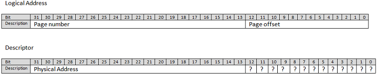
Mathematics of pages
When an instruction attempts to access a memory location, let`s say at address 0x00002345, the MMU will
treat that as a logical address. It will separate the address into a page number and an offset. If using a
paging system with a 4k page granularity, pages will be 4k each. By taking the address and dividing it by 4096,
you get a quotient of 0x02 and a remainder of 0x345, so the mmu would determine that the address points to page #2
at offset 0x345 within the page. The fact that page sizes are always powers of 2 is very convenient because
instead of doing a division by 4096, you can simply extract the right-most 12 bits as the offset and all upper bits
as the page number. So page_number = address>>12. offset = address&0xFFF.
Note that when using a logical address, you don't need to think about the page number and
offset. Using address 0x00002345 will yield page 0x2, and offset 0x345, and if you go 4k above that,
the address would be 0x00003345, so page 0x3 and offset 0x345. This is all done naturally.
Page tables
Page tables are tables of descriptors residing in memory.
Each descriptor is, for example, 8bytes long, or 64bit. Each descriptor are in order of pages. Descriptor 0
contains information about page 0 (0..4095), Descriptor 1: page 1 (4096..8191),
Descriptor N: Page N (N*4096..(N+1)*4096-1). A descriptor is a mapping to physical memory, it contains
a physical address. So let's say you need to access logical address 0x0000000000003DEF, the MMU will determine
that you want to access page 3, offset 0xDEF. The 3rd descriptor could hold the value 0x0123456789ABC000.
So that means that the MMU will map the logical address 0x0000000000003DEF tp physical address
0x0123456789ABC000 + offset 0xDEF, so 0x0123456789ABCDEF. See we have just transposed the offset over the
physical address? That is no coincidence. It is because the addresses in the descriptors will always be
a multiple of 4096, since pages can only start on a 4k boundary (for 4k pages that is). Therefore,
the 12 lower bits of the descriptor will always be zero. For that reason, those bits are always reused to
contain other information about the page such as permissions etc... But that is out of the scope of this article.
Basically, what this all means is that the mapping is like this:
PhysicalAddress = (PageTable[LogicalAddress>>12] & ~0xFFF) | (LogicalAddress&0xFFF).
The mapping is done transparently by the CPU!
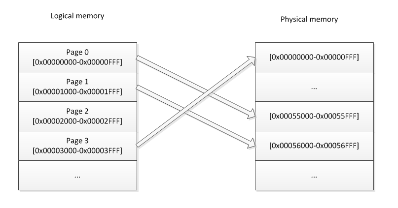
So far, paging is cool, but here is why it is powerfull: There can be many page tables in memory and
at any moment, the MMU can be instructed to use another table to change the mapping. Usually, in an operating
system, you want to use 1 page table per process. Let's say you write an operating system, and to make
things simple, you want the heap space of each process to begin at 0xBEEF1000. That is easy enough with paging
because you just create a page table for each of the processes and out an address in page number 0xBEEF1.
Obviously, you don't want each process to overwrite the data of the other processes, so the page 0xBEEF1
in each different page tables would point to a different physical location.
Note that if you only have 1g of RAM, the last accessible memory location would be 0x0FFFFFFF. But there
is no limit to the logical addresses (other than the architecture size, 32bits or 64bit) as long
as they map to a valid physical location (that is, under 0x40000000 if you have 1gig).
Since each process can have a full page table to themselves, it means that, as far as they know, they have a full
4gig of RAM (in the case of 32bit architecture) that they can access.
so let's say that you have 4 process and 4 gig of RAM.
- Process 1 maps the first gig of logical addresses to the 1st gig of physical addreses.
- Process 2 maps the first gig of logical addresses to the 2nd gig of physical addreses.
- Process 3 maps the first gig of logical addresses to the 3rd gig of physical addreses.
- Process 4 maps the first gig of logical addresses to the 4th gig of physical addreses.
If process 1 needs more memory, it sees that only the 1st gig of memory is used (because it only deals
with logical addresses and not physical addresses). So it will naively think that there is 3 gig of RAM left.
It will ask the kerl to map another gig of ram, but the kernel will say: Wait! there is no more physical
memory to which I can map these logical addresses. Well that's not entirely true. This is where swapping comes
in.
Page Swapping and Page faults
When the kernel runs out of physical memory so map to logical memory for a process, it will re-use a
physical location. There are many ways of determining which physical location to use, but for simplicity, let's
assume that this would be done randomly. As per our example above, all 4 process uses all the memory.
Process1 requests the kernel to map some physical memory to logical address 0x40000000. The kernel
has no more physical memory to hand out so it will pick a random location and will choose physical address
0x80000000 for example. This address is mapped to Page 0 of Process 3 already. So the kernel will modify the
page descriptor 0 in page table of process 3 and mark it as invalid. Remember the low 12bits that are unused
in the descriptor and I said there would be used for information about the descriptor? Well the "invalid" bit is
one of those 12 bits. The kernel will then take the full 4k residing at that physical location and store it
on the hard drive, in a swap partition (or file). It will then map the newly requested logical space for process 0
to that physical location. At this point, we have 2 process that have 2 different pages that points to the same
pysical location. Only one of those process has the page marked as being valid in its descriptor.
When execution resumes on process2, it could attempt to access page 0 of its logical space. When it does, the MMU
will see that the page is marked as invalid and will trigger a Page Fault exception. The kernel will then handle
the page fault exception. It will swap the 4k in memory with the one that was previously stored on the hard drive.
mark the page in fault as valid and mark the other one as invalid. And that is how swapping works.
Fragmentation
Another use of paging is for memory fragmentation.
Let's say that you have 2 process. and only 16K of memory, so 4 pages of 4k.
Process 1 is uing 2 4k buffers and has a mapping like this:
- Page0 = 0x0000
- Page1 = 0x2000
- Page2 = unused
- Page3 = unused
it means that Process 1 is using 8k of RAM. There is only 8K of RAM left.
Process2 comes in and wants to create a buffer of 8K. Obviously, it expects that
buffer to be contiguous memory. But that would be impossbile since there are only 2 4k
chunks left and they are not contiguous. Pagin will solve that. Process2 will have a mappint like this:
- Page0 = 0x1000
- Page1 = 0x3000
- Page2 = unused
- Page3 = unused
When process2 will access logical address 0x0000..0x0FFF, it will be transparently redirected in 0x1000..0x1FFF
and then when it continues to 0x1000...0x1FFF, it will be redirected in 0x3000..0x3FFF. So the logical memory
IS contiguous. This concept makes it very easy to avoid memory fragmentation as we allocate/deallocate
memory dynamically.
Translation Lookaside Buffer (TLB)
When an access to memory is requested, the CPU needs to translate the virtual address to physical address.
Like I mentionned above, this is done by walking through the page tables. This process adds a significant ammount
of time to the memory access because the CPU need to make one or several memory access just to decode the address.
So we are talking about more than 100% overhead here. To reduce the impact of this process, most CPU (if not all)
implement what is called the Translation Lookaside Buffer, or TLB. When a virtual address is translated, the result
is stored in the TLB. So when the next memory access is requested, the CPU will start by looking in the TLB. If a match
is found, then it doesn't need to look into the page tables. The TLB is inside the CPU, so accesses to it is very fast.
But the TLB has a limited size. When a new virtual address is translated, and the result cannot be stored in the TLB,
the CPU will choose a "victim" entry (the word victim is actually a word that some official documentation use) and
delete that entry to replace it with the new one. The algorithm for choosing the victim depends on the CPU implementation,
but would mostly be a "least recently used" type of algorithm. The TLB works kind of like a DNS cache but without TTL.
When a context switch occurs, the new running process might want to use a different page table for its own translation.
That is actually one of the many benefits of using a virtual memory system: so that each process can have their own
translation tables. The OS would then instruct the CPU to use another table by giving it the base address of the new table.
But the TLB still holds some translation that might not match the new table. We call those entries "stale entries". So when
updating the Page Table Base Address, we must also flush the TLB to remove all stale entries. But flushing the TLB could
add a significant ammount of processing. And what if the new process only needs 1 translation, and then we context-switch back
the the old process. There could be enough place in the TLB to store all the needed translation for both process. So
flushing the TLB is very inneficient in that case. That is why most CPUs will implement the concept of an
Address Space ID (ASID). On a context switch, ou would update a special register in the CPU to tell it the ID
of the currently running process (that would be the ASID). When the CPU adds an entry in the TLB, it will add
a "tag" to the entry, that tag would be the ASID. When a TLB lookup is performed by the CPU, any entries
tagged with an ASID that does not match the current ASID will be disregarded. So it would be
possible to have two identical translations but with different ASID. This illiminate the need to flush the TLB on
every context switch because stale entries will be tagged with a different ASID anyway. When the TLB becomes full,
the victims will preferably be entries for other ASID than the current one.
Some translations might need to be performed very often. Let's take, for example, the page containing the code for interrupt
handlers. That page needs to be accessed very fast, and we would want it to stay in the TLB all the time. Most CPUs
offer the possibility to mark some TLB entries as "permanent" or "locked". These entries will never be chosen as victims
if the TLB becomes full.
I've seen architectures, such as the AVR32, that doesn't do automatic TLB bookeeping. When a TLB miss occurs, they triger an exception and it is the duty of the OS to fetch and decode the page descriptor and load it in the TLB.
Addressing Space Limitation
Some people may wonder, if my CPU is a 32bit CPU, why can't I use 4gig of RAM?. This is because a 32bit CPU can only use a 32bit
integer as the address of a memory location. So it could address 4 gig of RAM theoritically. But you might have a video card
in your computer that has 1gig of RAM on it. That 1gig must be accessible by the CPU. So if you have 4 gig of RAM and 1gig in
the video card, it means that your CPU would need to access a total of 5gig of ram, but that is impossible.
You video card's RAM will be assigned a physical range of addresse. The 32bit adressing really just defines an addressing space.
This is kinda like if you were living on a very long street but there is a rule in your neighbourhood that
prevents you from using more than 2 digits on on the address plate of your house. Even though about 1000 houses
could be built on that street, after the 100th house, the next ones couldn't be assigned a house number because
the addressing space was all used up. In my example, I talk about a video card, but there are many other peripherals
that uses addresses from the addressing space.
Then you might wonder: how come I have a 32bit CPU and I can access my full 4gig on linux or windows 7? This is because
newer (they are actually old at the moment) CPUs have a 36bit addressing mode even though the CPU is 32bit. But the
OS must make use of that. WindowsXP did not use the 36bit addressing mode even if the CPU offered it. That is why it
was impossible to use your whole RAM on windowsXP