
Introduction
In the past couple of months, I've taken interest in the popular ESP8266 wifi enable uC. I've also wanted for a long time to start designing PCBs, so I decided to mix both interests and build an irrigation controller. I am no expert in PCB design nor any electronics for that matter. I'm a software guy. So this whole PCB design is done in a very amateur way and some of the experts out there might find many flaws in my design. But the important thing is that it does work as expected and most of all: I had a lot of fun and learned a lot of things while doing this. That project may look like a failure to some, but it is definitely a victory for me since I ended up learning things. And next time, I'll learn even more until I get good at it. That's the process I went through to learn about software design. I have to fail once before taking on the theory.
Overview
An irrigation controller is a pretty simple device. It's just a couple of relays, a microcontroller and a power supply. For my project, I decided to use 4 relays (to control 4 valves). The uC I chose is a esp8266, more specifically, the ESP-03 board. This brings wifi capabilities to my project. So the esp8266 connects to my network and with a multicast message, it advertises its presence. My New Home Automation system then picks it up and connects to it. From that point, it can control all 4 valves.
Part list
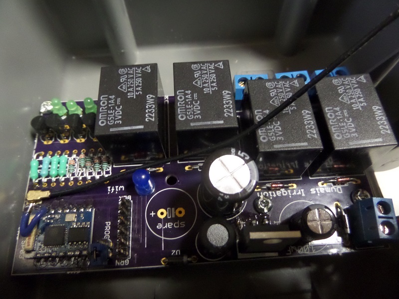
- My custom built PCB
- esp-03
- 4 G5LE-1A4 relays
- 1 LM2596
- capacitors (see diagram for values)
- resistors (see diagram for values)
- diodes (see diagram for values)
- uf.l SMD connector
- 2.4ghz adhesive antenna
- 4 MPS2907A transistors (PNP)
Power supply
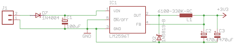
The ESP8266 needs a 3.3 VDC input and my valves need 24VAC. So I decided to supply my board with 24VAC, supply the valves (through the relays) directly and convert to 3.3vdc before the ESP8266 input. I had very limited experience in designing a power supply before this project. I still do. But I figured that using a diode and a capacitor, I could easily convert VAC to VDC. I then used a switched regulator to convert the high VDC down to 3.3v. I used the LM2596T regulator because I already had some pre-built power supplies that had that on it and found that they were working pretty well. The choice of capacitor to use was confusing. Looking online, I found many people using different values than what the datasheet suggests. So I experimented with a breadboard until I found a combination that worked (I know....). So bascially: 24VAC gets converted to something like 33VDC after going through 1 diode and a capacitor to smooth it out. Then Through a LM2596 to step down to 3.3V.
Antenna
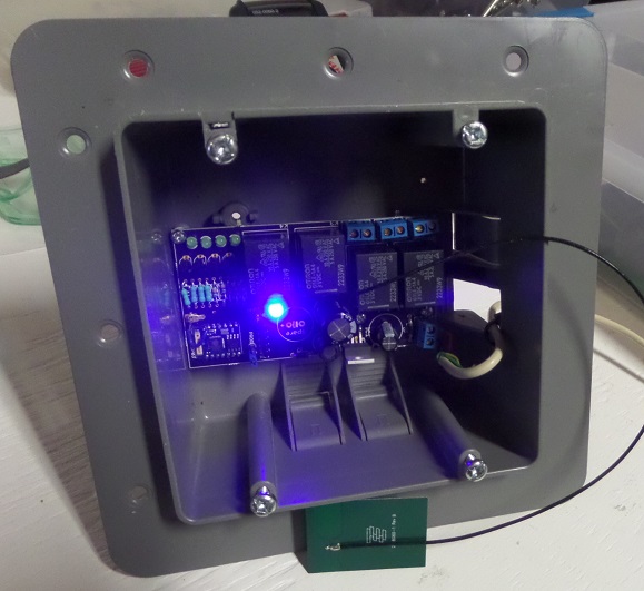
I wasn't expecting to use an external antenna at first. But when trying my board for the first time, I saw that it couldn't connect to wifi. When I designed the PCB, I added a trace to a SMD uf.l connector. But at that time, I had no connector nor any antenna on hand. So I was wondering if that trace could be the problem. So I cut it. But it still wasn't working. So I finally bought a connector and an antenna, soldered a wire on the board because the trace had been cut. And then everything worked out great. So yeah, you need an external antenna. The small ceramic antenna on the esp-03 won't do the job. Possibly because I put it too close to the power supply on my board? Or because I have no ground plane? I have no idea, that's something I'm gonna have to investigate.
Transistors
The choice of PNP transistors was because the ESP8266 GPIO are set high on boot. So I wanted my relays to stay opened during that time. I keep all GPIOs high when valves must be shut off, and pull the GPIO down when a valve needs to be opened. I did a lot of searching about where to put the load (my relay) in the circuit. Do I put it after the collector of before the emitter? Apperently it's better to put it after the collector. I still don't understand why though. So I still have some reading to do. But it works.
Firmware
I've already talked about the basics of the ESP8266 in my Led strip controller using ESP8266. article. It is using my custom made protocole "DWN protocol" to speak with my home automation software. So after my home automation software is connected to the irrigation controller, it sends 2-bytes commands to activate a valve or to turn it off. The firmware takes care of a couple of things like:
- Hard limit of 30 minutes "on" time for every valve. In case you forget to shut it off. If longer period is needed, then the controlling software will need to take care of it.
- Only 1 valve at a time can be opened. If the controlling software opens a valve, the irrigation controller will shut off any other opened valves.
- No valve sequence support. For example: V1 on for 10min, then V3 for 5min and then V2 for 1min. This needs to be done by the controlling software.
The sources:
Flaws
So far the biggest flaw I found is that I mixed up the RX/TX pins of the FTDI header. In eagleCAD, the part I was using for the header had to have its RX connected to the uC's RX pin. I didn't know that, I thought I had to reverse them. If I had looked at the FTDI pinout, I would have noticed it. Lesson learned. But it's not a big deal, I made an adapter that reverses both pins.
Also, like I said earlier, the wifi doesn't work without an external antenna. No big deal, I can use an external antenna. But I added that SMD footprint like 5 min before sending to the fab. I'm pretty glad I did that. The lesson learned here: anticipate for errors: put extra stuff in case you need it. That's obviously not good thinking for production but for a hobbyist like me, it's a good thing to do. Noticed the "spare" capacitor foot print on the board? hehehe.
Questions?
I've seen a lot of amateur projects like mine on sites like Hackaday and a lot of people always make the same comments so I figured I'd answer those questions immediately.
- Why did you do it this way instead of that way? Because I felt like doing it that way.
- Why not use this and that instead? Because that's not what I felt like playing with.
- Isn't this a fire hazard? I don't know! Is it?!?!?! Please tell me at youjustbuiltadeathtrapyoulunatic@dumaisnet.ca
- Why not use an Insteon EZFlora? I did. But I wanted to build an irrigation controller. So now my EZFlora is useless