
I recently installed an RGB led string under my kitchen cabinet. I wanted to way to control it using any web browser on a cell phone, tablet or desktop computer. There are many ways I could have achieved this but this time, I wanted to do it all by myself and design my first PCB. This is how I did it.
ESP8266
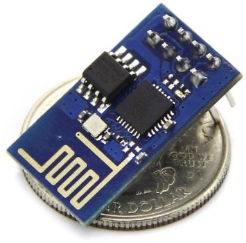
The ESP8266 is small cheap wifi microcontroller. It is a 32bit microcontroller with and external 1024kb or flash memory. There are tons of information out there about this chip so I won't dig too much into the basics.
When I discovered this board, I realized the potential it could bring to my home automation projects. I can now have multiple devices that talk to my central software (New Home Automation system) wirelessly.
Firmwares
The ESP8266 usually comes with a pre-loaded "AT" firmware. If it isn't, you can download it for free and upload it, using an FTDI cable, to your chip. The AT firmware is a simple firmware that lets you send "AT" style commands, like in the old days with modems, to control the chip. There's an AT command to connect to an access point, another to start a TCP server, another to send a packet, etc.
A lot of people use the AT firmware. This allows you to connect a another microcontroller to the ESP8266 using the UART pins and send commands to the device. But you can also write your own firmware and take advantage of the the 1024kb of flash on the chip. You have a few GPIOs and 2 UARTs. You don't need an external microcontroller.
Environment
To upload a firmware, whether it is the AT firmware or your own, you will need the flash tool. To build your firmware, you will need a complete toolchain. The esptool can be found at https://github.com/themadinventor/esptool/. Once you have downloaded the file, just copy it somewhere like in /usr/bin so that it is in your exec path. To upload a firmware, you must obviously obtain one or build one. The firmware is separated in a couple of file. If you are uploading the AT firmware, this should work (change /dev/ttyUSB8 for the serial port where your FTDI cable is attached):
esptool.py --port /dev/ttyUSB8 --baud 9600 write_flash 0x00000 boot_v1.1.bin 0x01000 v0.20/user1.bin 0x7c000 esp_init_data_default.bin 0x7e000 blank.bin
Programming
Keep in mind that the chip must be reset while GPIO0 is pulled low in order to enter the bootloader to accept a firmware update. To create your own firmware, you will need to download the toolchain. The following should get you going:
git clone --recursive https://github.com/pfalcon/esp-open-sdk
make STANDALONE=y
mv xtensa-lx106-elf /opt/
Now add /opt/xtensa-lx106-elf/bin in your PATH. Next, you will need a Makefile. I've created the following:
all: firmware

TTY=/dev/ttyUSB8
SRC = main.c
OBJECTS=$(SRC:.c=.o)
CC = xtensa-lx106-elf-gcc
CFLAGS = -I. -mlongcalls
LDLIBS = -nostdlib -Wl,--start-group -lmain -lnet80211 -lwpa -llwip -lpp -lphy -Wl,--end-group -lgcc
LDFLAGS = -Teagle.app.v6.ld

.c.o:
    $(CC) -c $(CFLAGS) $< -o $@

firmware: $(OBJECTS)
    $(CC) $(LDFLAGS) $(LDLIBS) $(OBJECTS) -o firmware.elf
    esptool.py elf2image firmware.elf

install: firmware
    esptool.py --port $(TTY) --baud 115200 write_flash 0 firmware.elf-0x00000.bin 0x40000 firmware.elf-0x40000.bin

clean:
    rm *.bin
    rm *.elf
    rm *.o
Again, remember to reset the chip with GPIO0 pulled low before invoking 'make install'. Here is a basic source file to build a firmware
#include "ets_sys.h"
#include "gpio.h"

void ICACHE_FLASH_ATTR user_init()
{
    gpio_init();

    PIN_FUNC_SELECT(PERIPHS_IO_MUX_U0TXD_U, FUNC_GPIO5);
    gpio_output_set(BIT5, 0, BIT5, 0);
}
Notice how the entry function is called user_init() instead of main(int argc, char** argv). This is because you are not running your firmware bare-metal on the board. There is an OS running in there and it will invoke user_init(). This is an event-based system. You cannot make an infinite loop like you would on another microcontroller. Instead, you let the OS run and hook your app to some events with callback functions. There is a way to create a timer and give the OS a pointer to your timer callback function. You can also give the OS a function pointer to a message handler and post messages to your app in order to receive messages in your message handler. If your code takes too much time inside a callback, the OS watchdog will reset your chip. So you cannot make infinit loops nor complex functions that do massive computations. You have to build your architecture around a single-threaded event-based system. Kindof like a javascript application.
The SDK, included in the toolchain, is pretty easy to use. For examle, to connect to a wireless access point, all you need to do is:
void ICACHE_FLASH_ATTR init_wifi(char ssid[32], char password[64])
{
    struct station_config station_config;
    wifi_set_opmode(1); // station mode. will connect to AP
    os_memcpy(&station_config.ssid, ssid, 32);
    os_memcpy(&station_config.password, password, 64);
    wifi_station_set_config(&station_config);
    wifi_station_set_auto_connect(true);
    wifi_station_set_reconnect_policy(true);
}

void ICACHE_FLASH_ATTR user_init()
{
    init_wifi("SSID","PASSWORD");
}
If you want to create an infinite loop, as I said previously, you cannot do this within a callback since it will block the os thread and the watchdog will reset your board. Instead, you need to post your self a message so that the OS will call your function everytime. For example:
#define TASK_QUEUE_SIZE 64
#define MAIN_LOOP_TASK_PRIORITY 1
os_event_t    main_loop_task_queue[TASK_QUEUE_SIZE];

// handle a message
static void ICACHE_FLASH_ATTR main_loop(os_event_t *events)
{
    // do something with the message
    ...

    // now post a message again to our self, creating an infinit loop
    system_os_post(MAIN_LOOP_TASK_PRIORITY, 0, 0);
}


void ICACHE_FLASH_ATTR user_init()
{
    system_os_task(main_loop, MAIN_LOOP_TASK_PRIORITY, main_loop_task_queue, TASK_QUEUE_SIZE);

    // post a message to ourself
    system_os_post(MAIN_LOOP_TASK_PRIORITY, 0, 0);
}
The Board
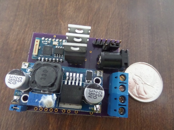
I'm not going to show my board diagram, because frankly, I'm a little ashamed of the work I did. This is my first PCB design and I'm still learning basic electronics. Bascially, I made a PCB with 3 mosfets, a step-down voltage regulator (12V to 3.3V) and a ESP-03 chip.
PWM
The chip supports software PWM for all GPIOs but I never was able to make it work properly. So I ended up writing my own software PWM. It's pretty straight forward, I just setup a timer and toggle GPIOs according to a duty cycle set by the user application. You can get my source code here:
DWN protocol
For each of my new Wifi devices to talk to my home automation server, I had to invent a new protocol. I could have used MQTT but I felt like my idea was even more simple. I created what I call the DWN protocol (DHAS Wifi Nodes).
The protocol is very simple. The wifi node broadcasts a JSON message containing its name and unique ID every 5 seconds on a multicast address at port 242. Whenever my home automation server sees such an advertisement, it will detect the source IP address of the broadcasting device and connect to the device's TCP server listening on port 242. Once the wifi device has a TCP client connected, it continue to send advertisements every 5 seconds and also sends heartbeats to the connected client. The DWN protocol does not define the format of payloads being exchanged between the home automation server and the wifi device. The DWN protocol is just a protocol that allows wifi nodes discovery.
Using such a system, my home automation can detect any wifi devices that gets turned on in my house and it will connect to it. Since the devices broadcast their name (ie: "IRRIGATION_CONTROLLER"), the server loads the appropriate "driver" or "module" for that device and starts communicating with them. This allows me to have a plug-and-play architecture. If I want to add a second led controller device, I just build one, turn it on and the home automation server automatically detects it and starts using it.
Future projects
This was my led controller board. I am planning on making a sprinkler controller with a esp-03 board with 4 relays, using the DWM protocol with my home automation server. I will also make a small device with a ESP-01 board with 2 input GPIOs to monitor my alarm system's relays. I currently monitor my alarm system's relay with an arduino setup as an ACM device plugged in the USB of my computer. I'd rather go wifi now. I would also like to build a device that would stay connected in my car. Onces I park my car in the garage, because of the DWN protocol, my home automation server will know when my car is at home and when it isn't. So as you can see, these esp8266 chips can be used for many things in the home automation world.